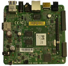
System Setup
Introduction
In this tutorial we will walk you through the steps necessary to develop Android apps for the Rho Board.
First we describe how to set up your development PC and build and run a simple Android app. These steps are not specific to the Rho Board, so we will refer to official Android documentation.
Next we run the same app on the Rho Board and finally we build a small example to exercise the RapberryPi compatible connector.
To have a simple, common setup, we assume you have a breadboard starter kit. (Similar to this: https://www.adafruit.com/products/1754 or this: http://www.amazon.co.uk/Electronic-Starter-Raspberry-Model-included/dp/B0082LD2B8 )
All but the final step can be run without the breadboard starter kit. Should you have different electronics connected to the RaspberryPi connector, the procedures are very similar, and the changes required should be minimal.
Recommended Setup
- Rho Board
- 12v power supply for Rho Board (optional - can be run from USB power)
- PC or Mac
- Ethernet cable.
- HDMI TV or monitor for Rho Board
- Mouse and/or keyboard for the Rho Board (optional)
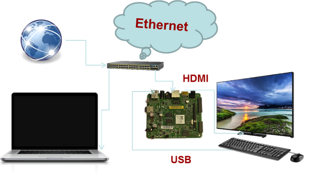
The following outlines what your development setup should be (power cables omitted):
PC Software Installation
Development of Android apps require at least two installs on your PC
First install the Java JDK, as mentioned here:
http://www.oracle.com/technetwork/java/javase/downloads/index.html
Then install Android Studio, which includes the Android SDK:
https://developer.android.com/sdk/index.html
First App
To ensure that your Android development environment is properly set up, we recommend that you first try running an example app consisting of pure Android Java code.
Follow for instance this tutorial:
http://developer.android.com/training/basics/firstapp/creating-project.html
Run app in simulator
This will ensure that the HelloWorld app is working correctly. See e.g.
http://developer.android.com/training/basics/firstapp/running-app.html#Emulator
Run app on OpenOTT
This assumes that your PC and OpenOTT is connected as described above. Now debugging between your PC and the OpenOTT needs to be enabled as follows:
- On the OpenOTT, open the Settings app and click Ethernet.
- Note down the OpenOTT’s IP address.
- Go to the bottom menu in the settings app, called MediaBox. Repeatedly click the “Build number” until it says “You are now a developer”
- In a terminal on your development PC, type “adb connect <openOTT IP>”, e.g. “adb connect 192.168.1.137”. Note: On Windows, the adb command is not installed in the system’s path, so you need to manually add it to your path or cd to it. It should be located in C:\Users\<your username>\AppData\Local\Android\sdk\platform-tools
- On the OpenOTT’s display, there should be a popup, saying “Allow USB debugging” – click “Always allow from this computer” and press OK.
- Now proceed running the HelloWorld app from before on the OpenOTT as described here:
http://developer.android.com/training/basics/firstapp/running-app.html#RealDevice
Electronics setup and test
For the following tutorial, we need to wire up the electronics for the project. For this first, simple example, we will use an LED as output and control it from the UI of our program. To set this up on the breadboard, do as follows:
- Connect pin 3 of the IO connector to the longest pin (+) of the LED.
- Connect to the shortest pin (-) of the LED to a 220 Ohm resistor. This resistor will protect both the LED and the GPIO pin from excessive current.
- Connect the resistor to any ground pin – e.g pin 6
- Now start the IO app, on the OpenOTT:
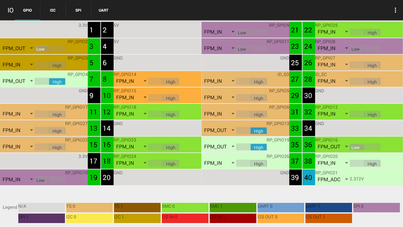
The IO app is a test app that can be used to get and set the values of the pins on the OpenOTT’s RaspberryPi connector. It can not, however, perform logic between the inputs and outputs.
To ensure that electronics is wired correctly,, configure pin 3 as output, and change its value back and forth between low and high – watch the LED turn on and off.
App that Accesses OpenOTT Hardware
Getting our feet slightly more wet, we will now turn the LED on and off from our own program. The IO app we used before is a fine example of how to use all the features of the IO connector, but its complex UI may make it a bit hard to understand, so we have prepared a minimalistic example, that has a very simple UI. Fetch the project from here (if you are not confident with using git as version control, just download and unpack the zip file)
https://github.com/OpenOTT/IOExamples
From Android Studio, chose the File/Open menu, navigate to where you unpacked the zipfile, and select the FirstExample project. Refer to you previous experience and compile and run the project on the OpenOTT board. This should present you with the following app UI:
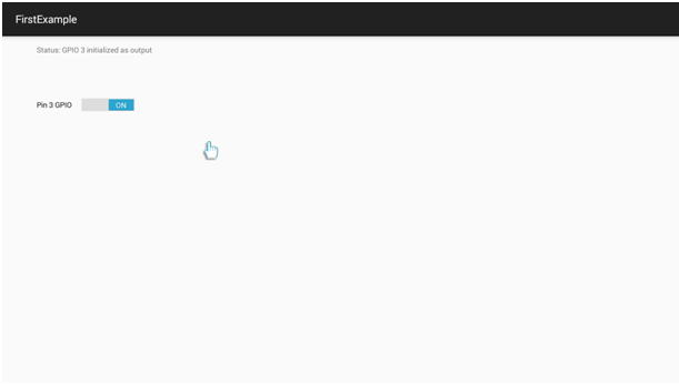
You should now be able to turn the LED on/off using this UI, rather than the IO app.
Code walkthrough
We assume that the previous Android tutorials have made you somewhat familiar with the general structure of an Android studio project, so feel free to investigate the example project.
To understand how your code that control physical hardware on the OpenOTT board, consider the following diagram:
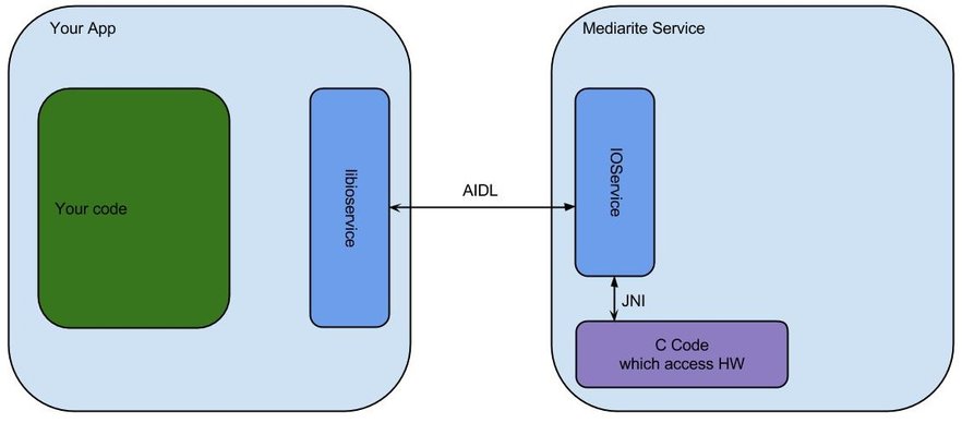
In Android terms, a service is a software component, which runs in the background, offering functionality to other apps without having a UI of its own. Futarque’s Mediarite service is exactly that – and one of the functionalities it offers is an IOService, which is used to access the IO pins of the Raspberry Pi compatible connector.
The way an Android app communicates with a service is through an IPC mechanism called Binder, which uses an interface language called AIDL. Fortunately you do not need to know about this, as we have created a library called libioservice, which maps regular Java methods to AIDL. But we do need to do two things: Instruct your Android project that it should use libioservice and create a connection to the Mediarite service.
Include libioservice
Using the libioservice is a two step process – first we instruct Android Studio to look in the Futarque Maven repository at BinTray. This is done with the following lines in the project’s build.gradle file:
maven {
url ‘https://dl.bintray.com/futarque/maven/’
}
Then we tell Android Studio that we want to use the library “libioservice” with the following line in the app module’s build.gradle file. This also dictates the required version of the library (0.110) and the format (.aar, which is the Android equivalent of a .jar file)
compile ‘com.futarque.openott:libioservice:0.110@aar’
Create Connection to Mediarite service
With this in place we are now ready to write some code to use the IO service. In the FirstExample project, all code is done in the HwExampleActivity.java file. As you should know by now, the onCreate method is the starting point for activities. First a listener is installed for the UI’s switch button – more on that later. The bottom part of the onCreate method says something like:
Intent implicitIntent = new Intent("com.futarque.mediarite.IOService");
List resolveInfo = getPackageManager().queryIntentServices(implicitIntent, 0);
if (resolveInfo == null || resolveInfo.size() != 1) {
mStatusText.setText("Status: No unique com.futarque.mediarite.IOService service found");
return;
}
// Get component info and create ComponentName
ResolveInfo serviceInfo = resolveInfo.get(0);
String packageName = serviceInfo.serviceInfo.packageName;
String className = serviceInfo.serviceInfo.name;
ComponentName component = new ComponentName(packageName, className);
// Create a new intent. Use the old one for extras and such reuse
Intent explicitIntent = new Intent(implicitIntent);
// Set the component to be explicit
explicitIntent.setComponent(component);
startService(explicitIntent);
mStatusText.setText("Status: Attempting to connect to Mediarite");
bindService(explicitIntent, mServiceConnection, 0);
Long story short, this tries to create a connection to the service named com.futarque.mediarite.IOService. Specifically, the final bindService() call starts an asynchronous operation whose result is sent as a callback to the provided mServiceConnection class, which is defined above as:
private ServiceConnection mServiceConnection = new ServiceConnection() {
@Override
public void onServiceConnected(ComponentName name, IBinder service) {
mIMediarite = IMediaRite.Stub.asInterface(service);
try {
mStatusText.setText("Status: Attempting access IOService");
mIOController = mIMediarite.getIOController();
mIOController.getGpioProvider();
IGpioProvider provider = mIOController.getGpioProvider();
mPin = provider.openPinNumber(3);
PioConfig cfg = new PioConfig();
cfg.mIsOutput=true;
mPin.setPioConfig(cfg);
mPin.setState(PinState.LOW);
mStatusText.setText("Status: GPIO 3 initialized as output");
mSwitch.setEnabled(true);
} catch(RemoteException e) {
mStatusText.setText("Status: Error creating IOController");
}
}
@Override
public void onServiceDisconnected(ComponentName name) {
mStatusText.setText("Status: Could not connect to IOService");
mIMediarite = null;
}
};
If the connection is successful, the onServiceConnected() method is called, and this is where the interesting stuff starts to happen – we get the IOController, get a IGpioProvider from it, configure pin 3 as output and set the pin to low. Finally we set the UI’s switch button to enabled – it was previously disabled (in the UI’s xml file) and thus could not be clicked until the IO sevice connection is made and the GPIO pin was properly configured. When the switch button is now clicked, the following code is now called:
mSwitch.setOnCheckedChangeListener(new CompoundButton.OnCheckedChangeListener() {
@Override
public void onCheckedChanged(CompoundButton buttonView, boolean isChecked) {
try {
if (isChecked) {
mPin.setState(PinState.HIGH);
} else {
mPin.setState(PinState.LOW);
}
} catch (RemoteException e) {
mStatusText.setText("Status: Error setting GPIO pin 3");
}
}
});
This very simply sets the GPIO pin’s state to the same state as the switch button.
The use of the IO library should be pretty straight forward – there is autbuilt help available from within Android studio and we are working on Javadoc documentation.
The part about the service connection may not be obvious, unless you are familiar with Android services, but there are plenty of documentation on this, for instance the official one:
http://developer.android.com/guide/components/services.html
For the moment, you can use the FirstExample as boilerplate code for new projects, but in the future we may wrap the service connection into a helper class in the libioservice.
We hope this tutorial has been interesting to you, and sufficient to get you started with OpenOTT hardware development programming.